 Up
Up
|
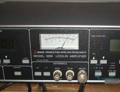
EG&G PRINCETON Applied Research model 5209 High Performance Single Phase Analog Lock-in Amplifier W/Manual!!!! Single-ended or true differential 10 nV to 3 V (with output expand) 13 fA/ÖHz (10-8 A/V) at 1 kHz The instrument includes a current preamplifier with two transimpedance settings and so can directly measure signals from current sources such as photodiodes. With an input impedance of down to typically only 25 W the resulting voltage generated across the source by the signal current is minimized for the very best performance. Continuous full-scale sensitivity control... As with all lock-ins the model Unique Walsh Function Demodulators... Squarewave demodulation is ideal for many applications, such as experiments using chopped light beams where the signal being detected is a square-wave, since the odd harmonics contain useful information. However in other cases the requirement is for "sinewave" or "fundamental" response where only signals at the reference frequency are measured. In theory, a squarewave can be modified to a sinewave response by inserting a low-pass or bandpass filter in the signal channel ahead of the demodulator. However this requires a highly selective filter in order to reject signals at the third harmonic without at the same time causing significant phase and magnitude errors for signals at the reference frequency. 5209 uses a modified form of switching demodulator, known as the Walsh demodulator, which multiplies the applied signal by a stepped approximation to the reference sinusoidal waveform. This gives a demodulator that does not respond to signals at the third and fifth harmonics, although it does respond to higher harmonics. A fourth-order signal channel filter is therefore included to reject these harmonics, giving a overall sinewave response. The advantages of the switching demodulator are thereby retained without the phase and magnitude errors associated with the use of highly selective filters. Choice of signal channel filter modes… In the usual sinewave response mode, the filter is set to the bandpass or low-pass modes. But what if you are trying to measure a signal at twice the reference frequency in the presence of a strong signal at the reference frequency? In this case, the filter can be set to a notch (band-stop) mode and tuned to the reference frequency, leaving the signal at 2F unattenuated and easy to measure. In addition to the main signal channel filter, a line-frequency rejection filter operating at 50/60 Hz and/or 100/120 Hz is also included, for elimination of troublesome line pickup. The combination of the Walsh demodulator(s) and the signal channel filter gives the instruments a dynamic reserve of up to 130 dB - implying that you can, for example, measure a signal of 1 µV in the presence of an interfering signal of more than 1 V. No other analog lock-ins deliver this performance. The output low-pass filters offer time constants in the range 1 ms to 3 ks, with all settings available at slopes of both 6 and 12 dB/octave. In addition, the units include a rear-panel output giving the signal at the output of the demodulator with a time constant of typically only 100 µs, for use in those applications such as tandem demodulation where the largest output bandwidth is required. The analog outputs from the demodulator , after filtering by the output low-pass filter, needs to be digitized by an analog to digital converter (ADC) for display or for transfer to the controlling computer. If this conversion is carried out asynchronously then the resulting values can display significant jitter. This is because the demodulator output contains not only the required DC level, but also signals at twice the reference frequency. When the output is sampled for conversion, this 2F signal means that some samples will be smaller and some larger than the mean. Of course, the 2F component can be reduced to any arbitrarily small value by increasing the time constant, but this reduces the response time to changes in input signal, slowing down data throughput. The model 5209 therefore offers a unique reference synchronous ADC trigger mode, which guarantees that the output is sampled at the same point relative to the reference waveform and thereby removes this source of error. In manual operation the backlit control setting indicators, the two digital displays and the analog panel meter makes the instrument very easy to use, with the settings of all the important controls being instantly visible. Six auto functions further simplify control adjustment, while red overload and reference unlock LEDs warn of conditions which will result in measurement errors. All the front panel indicators can be turned off for use in blackout conditions. The instrument includes GPIB (IEEE-488) and RS232 computer interfaces, allowing virtually all the controls to be operated, and all the outputs that can be displayed to be read, via simple ASCII mnemonic-type commands. The communications interface parameters, such as baud rate and GPIB address are set by front-panel controls, with no difficult DIP switches to adjust. Compatible LabVIEW drivers are available for those researchers working in that environment while the unit is also supported by the SRInstComms ActiveX control and SDK. It can also be used with our Acquire data acquisition software package, which allows non-programmers an easy way to log the instrument outputs to a PC file. The LabVIEW driver and a demonstration version of the software, DemoAcquire, are available for download from this site. * Money Order/Cashier Checks * Personal Checks will have to wait to clear first |