 Up
Up
|
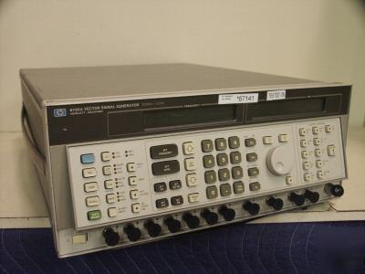
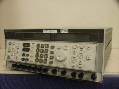
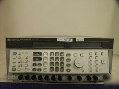
HP 8780A Vector Signal Generator, Synthesized. 10MHz To 3GHz With 1Hz Resolution. BPSK, QPSK, 8PSK, 16QAM, 64QAM, Digital Modulation, Pulse Modulation (1nS Risetimes) +10 to -100dBm Output. 700MHz of Arbitrary Modulation Using Vector OR I,Q Inputs. (Last Sold by HP for $71,400) With Option 002 (+10dBm Coherent Carrier Output - at Over $3,000 Value) And Option 064 (64 QAM Modulation - at Over $3,000 Value) The HP 8780A vector signal generator is a synthesized IF source with exceptional modulation for modern receiver and component testing. It is capable of modulation bandwidths almost 100 times wider than previous synthesizers. It has built-in mapping to simplify generation of common digital modulation formats. It's extra-wide modulation bandwidth comes from a vector modulator that effectively doubles baseband modulation bandwidths for 700 MHz of output modulation. The vector signal generator' wideband modulation is complemented with an unmodulated coherent carrier output for demodulation of test signals. The HP 8780A vector signal generator offers a wide variety of modulation using both digital and analog inputs. It generates many standard digital modulation formats like QPSK and 16 QAM and traditional modulation like FM, AM, and pulse. By combining the different modulation types, signals as diverse as Barker-coded radar pulses and Doppler-shifted satellite signals can be simulated. The HP 8780A vector signal generator is well suited for receiver measurements where wideband or complex modulations are required. It can be used as a calibrated transmitter to test modern radar EW receivers or communication receivers using vector I/Q modulation techniques. It provides a stable, coherent carrier for pulse measurement. * 10 MHz to 3 GHz IF testing * BPSK, QPSK, 8PSK, 16QAM, 64QAM, digital modulation and pulse * Direct-sequence spread spectrum modulation with chip widths to 7 ns * Pulse modulation with 1 ns rise times * 700 MHz modulation bandwidth using I/Q or vector * Wideband FM: over 200 MHz p-p deviations * Optional analog phase modulation for satellite telemetry * Tested Good With Guarantee. -10 /day after 10 day warm-up for internal reference <220 ms, <100 ms in fast mode (typical) Note: in the fast mode, output level accuracy is not specified. <5 x 10 -10 /(+5%-10%) (typical) RF Output Level Specifications (+12 to -100 dBm with Opt 064) ±2.5 dB for levels >=-30 dBm, ±3.5 dB for levels <-30 dBm and >-100 dBm Residual Output with RF Switch Off: More than 60 dB below the selected level (for levels >-40 dBm) Coherent Carrier Output Specifications Spectral Purity Specifications Residual SSB Phase Noise in a 1 Hz BW: Offset CW (typical) (typical) (typical) from Specified 10 MHz 10 MHz 10 MHz Carrier at 1 GHz to 3 GHz to 3 GHz to 3 GHz Note: Digital, vector, and scalar residual phase noise is the same as CW. ¹Typical phase noise for 10 MHz offsets is only applicable between 50 MHz and 3 GHz. Residual FM for CW, Digital, Vector or Scalar Modulated Signals (300 Hz to 3 kHz post-detection BW at 50 MHz carrier): Harmonics: <-35 dBc for output levels <= +7 dBm to 2.5 GHz and <=+1 dBm to 3 GHz Non-Harmonically Related Spurious Signals for CW, Digital, Vector, and Scalar Modulated Signals with Output Level Frequency Carrier Spurious Level The Agilent 8780A Vector Signal Generator supports four basic methods of modulation: Digital (including Pulse/Burst), Scalar, FM and Vector. These modulations can be combined simultaneously as shown in the chart below. For detailed specifications, see each of the individual modulation specification sections. AC Coupled Frequency Modulation FM 3 dB Bandwidth: 20 Hz to 12 MHz for deviations < 30 MHz peak-to-peak, and carrier frequency > 50 MHz Deviation Ranges: 50 kHz to 50 MHz peak-to-peak with 3 digits of resolution. (Typically up to > 250 MHz p-p deviation range is possible by overdriving the FM input.) Note: FM 3 dB and deviation bandwidths decrease at carrier frequencies below 50 MHz Sensitivity: 1V peak-to-peak for displayed deviation Sensitivity Accuracy: < 7.5% for rates 50 Hz to 6 MHz and deviations < 30 MHz peak-to-peak Residual FM for 300 Hz to 3 kHz Post-Detection BW and 50 kHz Deviation Range: < 200 Hz rms. (Not applicable with DC Coupled Frequency Modulation FM 3 dB Bandwidth: 10 kHz for deviations to 10 kHz peak-to-peak Deviation Ranges: 150 Hz to 150 kHz peak-to-peak with 3 digits of resolution Sensitivity: 1V peak-to-peak for displayed deviation Sensitivity Accuracy: < 10% for rates to 1 kHz and deviations 150 kHz peak-to-peak FM Distortion at 1 kHz Rate and 150 kHz Peak-to-Peak Deviation: < 5% Residual FM for 300 Hz to 3 kHz BW and 150 kHz Deviation Range: < 5 Hz rms. Modulation Types: BPSK, QPSK, 8PSK, 16QAM (64QAM with Opt 064), Arbitrary 2-state Simultaneous Digital Modulations I < Q: Available with all digital modulations Burst: Available with 2-state, BPSK, QPSK, or 8 PSK (Burst with 8PSK or 2-State are not available with Opt 064) Burst dc On/Off Ratio: > 50 dB at 140 MHz carrier (Typically the same 10 MHz to 3 GHz) Clock Input Modes: Single, separate I and Q (except with Opt 064), or asynchronous Data Input Parallel Data Rates: 0 to 150 MHz clocked (except 64QAM), 0 to 100 MHz clocked 64QAM (with Opt 64) 0 to 50 MHz asynchronous (all digital modulations) Serial Date Rates only with Opt 064): 0 to 150 MHz clock and data lines for 0 to 25 MHz 64 QAM symbol rate Thresholds: ECL (-2V termination), ground or variable -2.5V to +2.5V in 100 mV resolution (0V termination) Timing Requirements-Set up time: > 3 ns Thresholds: ECL (-2V termination, ground or auto -2.5V to +2.5V (0V termination) Data and Clock Drive Requirements: 0.3 to 3.0V peak-to-peak. The digital data is clocked on the leading (positive) State dc Accuracy at 140 MHz carrier and <= +7 dBm levels (typically the same over 10 MHz to 3 GHz): ±1% of full scale I and Q values for BPSK, QPSK; ±2% of full scale I and Q values for 16QAM, 2-State, alternate Spectrum Filter: Four internal baseband filters to limit spectrum are automatically selected depending upon carrier frequency. Provision is made for user-supplied baseband filters. Carrier Frequency Nominal Filter Full range with no internal > 350 baseband filtering Pulse dc On/Off Ratio: > 50 dB at 140 MHz carrier (typically the same over 10 MHz to 3 GHz) Pulse Data Input Level: ECL (-2V termination), ground, or variable -2.5V to +2.5V in 100 mV resolution Pulse Data Drive Requirement: 0.3V to 3.0V peak-to-peak Pulse Data Input Impedance: 50 ohms nominal Typical Pulse Rise/Fall Times (10% to 90%): <= 1 ns with no internal baseband filtering Typical Minimum Pulse Width: < 7 nc Traditional amplitude modulation (with nominal levels 6 dB below the selected output level, and depths from 0% to 99%) can be generated when a 0.5V dc offset is added to the scalar input. 0V to 1V on the scalar input scales the vector signal generator output from off to full scale. Sensitivity: 0 to +1V for 0 to full scale envelope modulation Scalar dc Accuracy: < 2% of full scale input at 140 MHz carrier and for +7 dBm levels (typically < 2% from 10 MHz to Scalar dc Residual (Residual I and Q Output for 0 Volts Input): < 1% of full scale I and Q at 140 MHz carrier and <= +7 dBm levels (typically the same over 10 MHz to 3 GHz) Frequency Response: dc to 500 kHz (-3 dB) at 1 GHz carrier frequency Input Impedance: 10 k ohms nominal Vector Modulation (Using Analog I/Q Inputs) Frequency Response: dc to 350 MHz (-3 dB) at 1 GHz carrier frequency (typically > 350 MHz from 400 MHz to 3 Vector dc Accuracy: <1.5% of full scale vector inputs at 140 MHz carrier and <= +7 dBm levels and Ie2 + Qe2^1/2 <= 0.5V (typically the same over 10 MHz to 3 GHz) Vector dc Residual (Residual Output for 0V I and Q Input): < 1% of full scale vector inputs at 140 MHz carrier (typically < 1% from 10 MHz to 3 GHz) Sensitivity: ±0.5V into 50 ohms with 50 ohms source impedance for ±100% of full scale magnitude Input Impedance: 50 ohms nominal SWR: <1.5:1, dc to 350 MHz (typical) Typical Accuracy versus Modulation Frequency for Selected Carriers: Carrier Modulating Amplitude Crosstalk Frequency Flatness Between I and Q 140 MHz 1-40 MHz < 0.15 dB <2% 500 MHz 1-40 MHz < 0.15 dB < 2% 1.5 GHz 1-100 MHz < 0.3 dB < 4% 2.5 GHz 1-100 MHz < 0.3 dB < 6% Remote Programming Specifications All functions are HP-IB programmable except the line switch. The Agilent 8780A can output over the interface, frequency and output level settings, error/malfuntion codes, and operational status codes. Interface Functions: SH1, AH1, T6, TE0, L3, LE0, SR1, RL1, PP1, DC1, DT0, C0 48 to 66 Hz: 100, 120, 220, 240 Vac (+5%, -10%) 360 to 440 Hz: 100 or 120 Vac (+5%, -10%) 177 mm H x 425 mm W x 637 mm D (7.0 in x 16.7 in x 25.1 in) All Items sell with 5 days right of return, and 15 days GUARANTEE on all parts and labor. |