 Up
Up
|
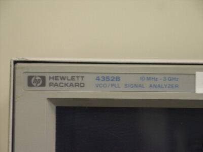
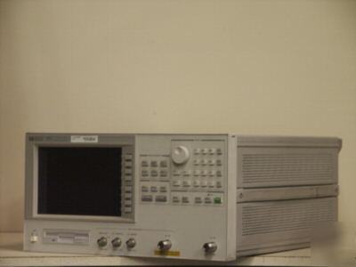
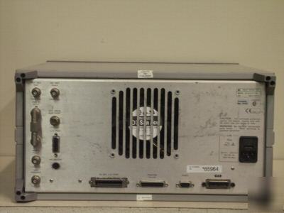
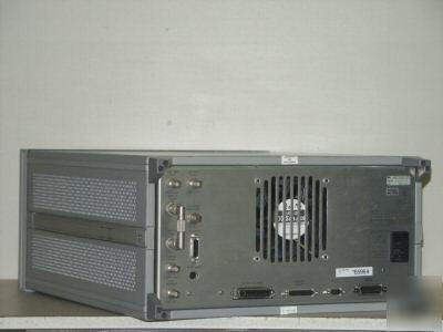
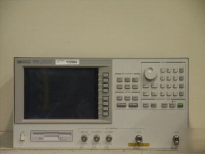
HP 4352B VCO/PLL Signal Analyzer, 10 MHz - 3 GHz. Resolution: 1kHz , Excellent Phase Noise Performance (-157 dBc/Hz at 1 MHz offset) Operates in Either Signal Analyzer or VCO Tester Modes up to 3 GHz . Part of the 4352S System. When configured with the HP 43521A downconverter unit, system can operate from 10 MHz to 12.6 GHz. Provides and controls the DC power supply, the low noise DC control voltage source and the 1 kHz signal source necessary for VCO tuning characterizing. Automatic measurement capability and power analysis functions are included. * Evaluates the characteristics of VCOs and PLLs that are essential to designing local oscillators used in RF wireless communications equipment * Operates in either Signal Analyzer or VCO tester modes up to 3 GHz * When configured with the HP 43521A downconverter unit, system can operate from 10 MHz to 12.6 GHz * Provides and controls the DC power supply, the low noise DC control voltage source and the 1 kHz signal source necessary for VCO tuning characterizing * Excellent phase noise performance (-157 dBc/Hz at 1 MHz offset) * Automatic measurement capability and power analysis functions are included • < 20 msec at 0.1 % error (typical) ≤ 2 GHz, ≤ 15 dBm) • ±1 dB (@ other conditions) • ±0.2 dB (@ 1 GHz, -5 dBm, typical) Number of measurement points per sweep The 4352B can compensate for the RF power level loss of the cable connecting the DUT output terminal and the 4352B RF IN connector when • ±(1 kHz + Time base accuracy of the external Number of measurement points per sweep Phase noise (carrier-to-noise ratio) The phase noise of signal generator isn’t • ±4 dB @ 100 Hz - 1 kHz (typical) • < -95 dBm (@ RBW = 30 Hz, typical) • < -75 dBm (@ RBW = 3 kHz, typical) • ±2 dBm (@ -5 dBm, typical) • 100 MHz to 3 GHz measurement range • 2 MHz, 20 MHz, MAX (see table 1) • Measurement range ÷ 40000 [Hz] • ±(Measurement range x 0.1% + Time base accuracy of the external signal generator) • Time base accuracy of the external signal • ±(2% of reading + 0.5% of measurement • ±0.8% (typical after FM deviation cal.) • LP filter: 3 kHz, 15 kHz, 20 kHz • <3 Hzrms (@ 300 Hz - 3 kHz bandwidth) • ±(0.2% of reading + 100 µA) • Built-in 3.5” flexible disk drive (720 kB or • Volatile RAM disk memory (512 kB) • Data and memory - ASCII, BINARY 24-bit parallel digital I/O port • I/O: 8-bit I/O, 16-bit output • PASS/FAIL signal, SWEEP END signal, • Output signal: VGA (640 x 480) • 90 V to 132 V or 198 V to 264 V, • 425 mm (W) x 235 mm (H) x 553 mm (D) All Items sell with 5 days right of return, and 15 days GUARANTEE on all parts and labor. If in order to comply with our guarantee, we need to refund your money, you will get a FULL refund for the price of the unit... If you need to make use of the 15 days Guarantee - We will fix, or replace, your unit. In case every attempt to fix or replace it fails, we’ll refund your money. Be sure to add me to your favorites list! |