 Up
Up
|
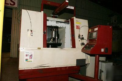
HUFFMAN MODEL HS4 5-AXIS TOOL GRINDER This machine was originally manufactured by S.E. Huffman Corporation. It is a model HS-4. The machine was retrofitted by CNC Machine Sales to update the machine with a new CNC controller unit with AC servos and motors and provide a mechanical rebuild of the machine. The Huffman HS-4 grinder has five axes of movement. The grind wheel is mounted on a combination of a vertical axis (Z), horizontal axis (Y), and rotation axis (B). The part is located on a rotary table (C) that is carried on a horizontal axis (X). These five axes (X, Y, Z, C and B) are under full servo control. The X, Y, and Z axes are driven by motors that are direct coupled to 5 pitch (0.200" per rev) screws. The machine zero locations are established when the machine is referenced. The machine zero for the X and Y axis is located with the grind spindle, when at 0.0 deg. vertical, is located on the table center. The machine zero position for the Z axis is set when the axis is at home position. When the machine is referenced, the axes go to positions listed below: - Machine reference position: +6.8836" - Travel limits machine coordinates: +7.63 to -3.52" - Machine reference position: +3.7095" - Travel limits machine coordinates: +6.005 to -6.25" - Machine reference position: 0.0 - Travel limits machine coordinates: +0.44 to -9.12" - Machine reference position: 90.0 - Travel limits machine coordinates: +1.0 to -160.0 deg. The X and Y axis part zero locations are set to zero with the grind spindle when vertical (0.0) is centered over the rotary table (C axis). This is the same as machine X and Y zero. The grind spindle mounted on the machine is a variable speed unit with a range of 100 to 7200 RPM at the motor or spindle. The spindle is belt driven by the motor through a pulley arrangement with a 1 to 1.94 ratio. The motor is a US Electrical Motors, Unimont 125, Model A982A with a 15HP rating. The machine has the ability to establish reference positions for X, Y, Z, B and C axes through a process of homing or referencing the machine whenever power is first applied to the machine. With the battery backed up absolute encoders on the machine, the reference positions do not have to be established when ever applying power to the machine. When power is first applied to the machine, the CNC control must first be taught where each axis is relative to each other and to the machine itself. This process should be done only one time after power up. When the emergency stop button is pressed and later released, the machine still remembers the axis positions and a homing cycle is not required. With the battery backed up absolute encoders on the machine, this is even true when power is removed from the machine. MANUAL REFERENCE POINT RETURN PROCEDURE: 1. Manually jog the axis off its home position 2. Select home mode with the mode selector push-button (Operators Panel) 3. Select the desired axis with the axis select push-button (X,Y,Z,B,or C) 4. Push + jog push-button, At this time the axis will move to its 0 position 5. Repeat steps 3 and 4 for each axis - Max Rapid Move Feedrate: 150 IPM - Max Cutting Feedrate: 150 IPM - Manual Rapid Feedrate: 150 IPM - Max Rapid Move Feedrate: 120 IPM - Max Cutting Feedrate: 120 IPM - Manual Rapid Feedrate: 120 IPM - Max Rapid Move Feedrate: 150 IPM - Max Cutting Feedrate: 150 IPM - Manual Rapid Feedrate: 150 IPM - Max Rapid Move Feedrate:1800 DPM - Max Cutting Feedrate: 1800 DPM - Manual Jog Feedrate: 720 DPM - Manual Rapid Feedrate: 1800 DPM - Max Rapid Move Feedrate: 1000 DPM - Max Cutting Feedrate: 500 DPM - Manual Jog Feedrate: 360 DPM - Manual Rapid Feedrate: 500 DPM 20" Diameter T-Slotted Rotary Table (C-Axis) |